Test fit requests often precede actual T.I. contracts, and are typically a very basic per-square-footage fee. As such, budgets rarely allow for 3D build-out of existing spaces, and the goal is primarily to get area summaries and office/workstation counts against the tenant’s programmatic goals.
Here are guidelines to creating Test Fit models within the budget:
Leverage the CAD background:
Most building owners have legacy CAD files of their building stock, hopefully up-to-date. Use as much as possible directly printed as backgrounds to the modeled Proposed New Work
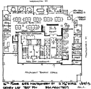
NOTE: Even handdrawn plans can be used as backgrounds – insert the image and scale using a known dimension (typical 3′-0″ door, for example).

Use FLOORS to mask the existing CAD layout:
Use a floor to both calculate the Area of Work, and to cover over CAD linework of existing layout. Use subset floors to define ‘zones’ if needed.
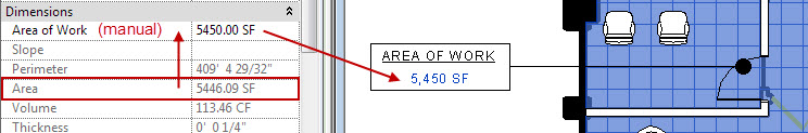
Use Floor tags (TI Area of Work or TI Program Area) to list overall/subarea square footage. NOTE: The tags require manually typing in the area, to ’round up/down’ to an appropriate whole unit.
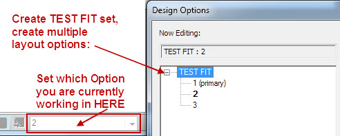
Create Design Options:
Create a TEST FIT set, and create the number of Options you anticipate evaluating (you can add/delete later, if needed).
Create elements CONSISTENT TO ALL OPTIONS in the Main Model (Floor to define overall area, for example). All other work should be modeled in the specific Option desired.
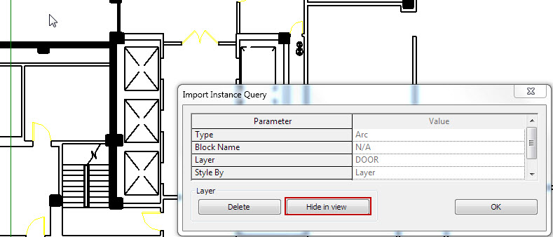
NOTE: As CAD walls/doors will not be modeled, use Detail Lines in the option to trace over intended DEMO elements with dashed linework.
Copy/Paste in Schematic FF&E Content:
The project template will NOT be preloaded with furniture – you need to select what you need from the Firm’s RESOURCE FF&E file (my recommendation for content management). Copy/paste to the Main Model of your project, off to the side of your area of work. Be active in appropriate Design Options when placing the components, to assign them correctly to your various options.

 NOTE: Schematic TI content often has convenient parameters to allow maximum flexibility from a single family (manufacture specific content will never be this flexible). Create new types in your project if a variety of sizes are needed.
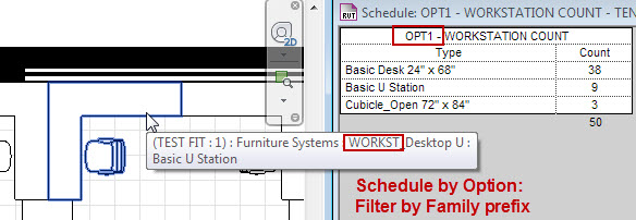
Schedule Workstation Counts:
Create Schedules for each layout Option, and filter by the “Starts with..” prefix WORKST.

Awesome idea to use floor that way. FYI, you can change the units that the tag uses by selecting the parameter in the label in the tag family and down at the bottom is a hand pointing to a # sign. Click that and you can change the units of how that parameter reports just in that tag.
Of course I got ahead of myself. It looks like you can’t tag the area of a floor… Am I missing something?
Yeah, Floors don’t give you AREA as a tagable parameter. Whaaaa?
I used a shared parameter to get around that, and it allows for appropriate rounding.
Pingback: isabel marant
Pingback: Trackback